Philips B0IF95U
Introduction
 I
bought this interesting little set from Past
Times Radio, along with two others, for £60 total (including carriage).
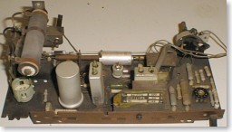
It is a small plastic cased 3-valve plus rectifier set receiving MW only. With
Philips model numbers, the first digit indicates the quality or price range,
on a scale of zero to nine. This set is a zero. It was probably made in the
late 1950s.
I
bought this interesting little set from Past
Times Radio, along with two others, for £60 total (including carriage).
It is a small plastic cased 3-valve plus rectifier set receiving MW only. With
Philips model numbers, the first digit indicates the quality or price range,
on a scale of zero to nine. This set is a zero. It was probably made in the
late 1950s.
The supply voltage rating is 220V only, so this
is obviously a European rather than UK set. However the tuning scale is still
printed in English.
As received, the set was in tidy condition. The
white front section was dirty and was also detached from the rest of the cabinet
(only the knobs stopped it falling off). The back is hardboard rather than the
usual cardboard and has survived well. The mains cable had been cut off close
to the set. I don't think this was done by Past Times Radio because the other
sets I bought still had their cables, so it must have been through the hands
of a second-hand dealer or charity shop previously.
Initial Assessment
 The
valve lineup must have been an attempt to use up whatever was in the Philips
stores! UCH81, UBF80, UCL82 and UY42. Most sets of this type would use a UBF89
rather than a UBF80, and a UY85 instead of a UY42. Many would also use a UCL83
output valve because it has a lower power output.
The
valve lineup must have been an attempt to use up whatever was in the Philips
stores! UCH81, UBF80, UCL82 and UY42. Most sets of this type would use a UBF89
rather than a UBF80, and a UY85 instead of a UY42. Many would also use a UCL83
output valve because it has a lower power output.
One of those horrible black capacitors that Philips
use had partly melted onto the PCB, and has sprayed some of its innards out
of one end onto a trimmer capacitor. Quick checks with a meter showed that the
dropper resistor and output transformer were OK.
However the dropper resistor did not look original.
It was a 2k-ohm component with an adjustable tapping - not the sort of thing
that would be used for production. The wiring to it looked like 1960s lighting
flex, and was discoloured and brittle. I also noticed that the UY42 was Mullard
branded, whereas the other three valves were Philips. It also looked newer,
which suggested that the valve and dropper had failed in the past and been replaced.
Enquiries around the usual sources of service information were unsuccessful.
Although this set is hardly complex, I thought a diagram would be useful. I
looked through the Philips diagrams on the Radio
Italiane II CD-ROM, and found the B0I00U, which looked very similar apart
from the voltage selector arrangements. The valve types were not shown, but
the rectifier is obviously not a UY42 because it has a pin numbered 9. However
it was the best I was going to get, so I printed a copy.
A copy is reproduced here (note this is at much
lower resolution than on the CD-ROM, so it will fit on the page).
Disassembly
This should be straightforward. I removed the
off/on/volume knob and the back, then released the two screws holding the PCB
and the two holding what passes for a chassis into the cabinet. The tuning knob
is retained by a spring clip inside the cabinet. With this removed it should
just pull off the shaft.
Note that I said, "should". This one
was jammed solid onto the shaft. The shaft was rusty, and had probably rusted
inside the knob too. Applying pressure from inside with a screwdriver had no
effect. Obviously if I tried to prise the knob off from outside I would just
break it. At this stage I removed the valves for safety.
I applied some WD40 to the shaft and left it
to soak in for a few minutes. No luck. I left it for a while longer, but it
still didn't want to move. However the pressure being applied was bending the
bracket. What was obviously needed was some method of pushing the knob sleeve
away from the bracket, without straining anything else. I managed this using
a small pair of pipe grips with the outsides of the jaws between the parts and
pulling the handles apart. This had the desired effect. The knob was still quite
tight, but the WD40 had reached all the way down so clearly this had helped.
The only things stopping the innards being withdrawn
now were the wires to the speaker and the aerial connection clip. Rather than
desoldering these, I removed the screws holding the components in place and
took the whole lot out. I then disconnected the speaker. Maybe Philips had lots
of grey wire to use up too, because they used this colour for everything.
Aerial and Tuning
 The
"aerial" is a piece of metal foil stuck in the top of the cabinet,
connected to the circuit with a piece of wire and a spring clip. A similar piece,
presumably "earth", was stuck in the bottom, connected via a spring
on the bottom of the PCB.
The
"aerial" is a piece of metal foil stuck in the top of the cabinet,
connected to the circuit with a piece of wire and a spring clip. A similar piece,
presumably "earth", was stuck in the bottom, connected via a spring
on the bottom of the PCB.
The set uses permeability tuning, with two coils
for aerial tuning and oscillator mounted along the edge of the PCB. A drive-cord
arrangement pulls a couple of ferrites through the cores. Only the oscillator
coil is shielded.
The PCB has a number of extra tracks and holes
that are not used in this set, including some that look like they are for mounting
a variable tuning capacitor. It was probably designed for use in more than one
model.
Repairs
 The
first thing to deal with was the melted black capacitor. This was connected
straight across the mains input. The circuit diagram showed it was 100nF (0.1uF)
and the markings agreed. The original was only rated at 500V DC (no AC rating
shown), which seemed rather low. I used one of those yellow 1000V LCR types
as a replacement, but before I fitted it I removed the beehive trimmer that
had been on the receiving end of the original capacitor spitting out some of
its innards.
The
first thing to deal with was the melted black capacitor. This was connected
straight across the mains input. The circuit diagram showed it was 100nF (0.1uF)
and the markings agreed. The original was only rated at 500V DC (no AC rating
shown), which seemed rather low. I used one of those yellow 1000V LCR types
as a replacement, but before I fitted it I removed the beehive trimmer that
had been on the receiving end of the original capacitor spitting out some of
its innards.
The muck was just wax so I was able to remove
most of it with a screwdriver before cleaning the rest off with contact cleaner
and paper tissue. I did this without removing the seal or disturbing the setting.
Once this were refitted, I replaced the mains cable. I also removed the earth
spring temporarily because it tended to fold over and short to other components
when the PCB was placed on the bench. I couldn't see anything else amiss, so
decided it was nearly time to show it some electricity.
First though, I checked the smoothing capacitor
with the capacitor reformer, because I know the capacitors Philips used in the
B2G81U (and other sets based on the same chassis) are not very reliable. This
one seemed OK.
Connecting the Mains
I reconnected the speaker, refitted the valves
and connected a length of flex to the aerial socket. A resistance check across
the mains cable showed open circuit. I wiggled the valves, which identified
the fault as the connection between the UCH81 and its base. I applied some contact
cleaner to the base then plugged and unplugged the valve a few times to clean
the contacts.
I connected the test meter across the HT as usual,
and connected the set to the mains via the lamp limiter. The limiter would drop
around 20-30V if the set was working, which would compensate temporarily for
running a 220V set from 240V mains.
It worked. It sounded very thin, and the HT was
only about 140V. I checked the grid of the output valve - no positive volts
here. The surge limiting resistance is 720 ohms, which is rather higher than
the usual 200 ohms or so, but this is part of the 2000 ohm replacement so it
was whatever was left over when the tapping had been set for the heaters.
The lamp limiter was dropping around 25V as expected,
leaving almost exactly 220V for the set. The voltage at the top of the heater
chain was 99V. I decided to check the voltage ratings of each heater and make
sure this was correct. Since I had a movable tapping the plan was to set it
to give the correct heater current at 245V mains rather than 220V.
The three U*80 valves were in the Mullard Maintenance
Manual and had heater voltages of 50V (UCL82), 17V (UBF80) and 19V (UCH81).
The UY42 data was rather more difficult to locate. It wasn't in the Mullard
book, or Brimar, or a few others. Eventually I found it in Bernards Volume 2.
The heater voltage is 31V, giving a total of 117V.
I switched the lamp limiter out of the circuit
and the heater voltage rose to 114V. Close enough. Obviously the repair had
been done here in the UK. The set also sounded a lot better, as would be expected
with the valves operating properly, and the HT rose to about 170V.
UY42 Rectifier Valve
Since I had so much trouble locating data on
the UY42, I decided to look a bit closer at the specs. According to Bernards,
the maximum RMS anode voltage is 110V! That seemed most odd, so I looked for
further verification (assuming it was a printing error).
 The
TDSL (Tube Data Sheet Locator) program from Duncan Amplification did not contain
any data for the valve, but did link to a data sheet at frank.nostalgiaair.org.
This data sheet was from a Philips manual, and confirmed the maximum input voltage
of 110V. It also described the valve as a "High vacuum half-wave rectifier
for 110V mains", which is conclusive enough.
The
TDSL (Tube Data Sheet Locator) program from Duncan Amplification did not contain
any data for the valve, but did link to a data sheet at frank.nostalgiaair.org.
This data sheet was from a Philips manual, and confirmed the maximum input voltage
of 110V. It also described the valve as a "High vacuum half-wave rectifier
for 110V mains", which is conclusive enough.
The first page with the non-English parts omitted
is reproduced (much smaller than the original) here.
So what was it doing in a set designed to operate
from 220V? It was definitely the right component, according to the label inside
the back cover. So either Philips are being very brave - maybe they know something
we don't (they did made the valves, after all). Or maybe it was a "Friday
afternoon" decision - in other words a cock-up?
So I had two choices. I could leave it as it
was, and hope the UY42 continued to stand up to this sort of abuse. This would
be the right decision from a "restoration" point of view.
Or I could replace the UY42 with a UY41. This
has almost the same pin connections and even the same voltage heater. This would
be right from a reliability point of view.
Since the set had clearly already had one failure
in that area I was inclined towards the second option. Certainly I would be
very worried about continuing to run it is it was, but I was still undecided.
I asked the opinions of other collectors on the Vintage Wireless email list
and by direct email. The result was almost unanimous - fit the UY41.
One person pointed out that the modification
was easily reversible (just change a valve) at a later date if desired. Another
mentioned that in his early 1960s Mullard book the UY41 was listed as a direct
replacement for the UY42. A third person said that if I was to leave the UY42
in place I would have to add fuses to the circuit to prevent the risk of further
damage if it does fail, which is a more messy and involved modification than
just changing the valve. Thanks everyone, for helping me to decide.
The only question outstanding is why Philips
bothered to produce the UY42 at all, when they already had the UY41. Later versions
of this set (B0X15U etc) used a UY89 rectifier, which is more sensibly rated
at 250V.
Replacing the Valve
Although all the active pins on the UY41 are
the same as the UY42, there was one subtle difference. The UY42 data has two
of the spare pins labelled as IC (internal connection) and the other two as
unused. The UY41 has all four labelled as IC. This would be irrelevant, except
that in this set a PCB track from the heater connects to one of the UY42 unused
pins as a convenient way of routing it.
I examined four UY41 valves from my stock and
found that although the pin is not actually connected to any of the active elements,
it is connected to a wire in close proximity to the anode. I didn't know what
the effect of connecting this wire to a lower AC voltage than the anode would
be (given that the anode is hotter and the two are in a vacuum) and I decided
I didn't want to find out the hard way! I unsoldered the valve holder from the
PCB, removed the offending contact, then refitted the holder to the PCB.
Dropper Resistor
I also rewired the dropper using PTFE insulated
wire covered with heat-resistant sleeving (both "donated" by w*rk
:). The set was then tested again. The sound was still rather thin and the HT
was still only about 170V. This was due to the 850-ohm surge limiter section.
In the circuit of the B0I00U I was using for reference, this resistor was 200
ohms. I looked as a few other circuits using a similar valve lineup, which confirmed
that somewhere between 100 and 250 ohms was about right. The UY41 data sheet
showed the minimum value for 250V AC and a 32uF smoothing capacitor to be 160
ohms.
I had a number of 330-ohm wirewound resistors
in stock, rated at about 5 watts. One of these in parallel with 850 ohms is
about 220 ohms. I mounted this underneath the main dropper contacts. With this
fitted the HT was about 220V and the sound was a lot better.
Obviously the sound quality from a set like this
won't be that good. In particular it lacks bass, but then what can we expect
with such a small output transformer (it's only about 30mm square)!
Crackles
After a few minutes another problem became evident.
The set would crackle and vary in volume (alternating between loud and quiet
randomly), but only when tuned into a strong station.
As a quick test I replaced the UCH81, UBF80 and
UCL82 valves. No change, so it wasn't a valve. I refitted the originals. It
didn't come and go as the board was gently flexed and as parts were moved, so
it didn't seem to be an intermittent connection.
 My
first thought was that this was something to do with the AGC. I connected the
'scope across the AGC decoupling capacitor (C10). The voltage did indeed vary,
however it was difficult to work out whether this was the fault or just a result
of the fault.
My
first thought was that this was something to do with the AGC. I connected the
'scope across the AGC decoupling capacitor (C10). The voltage did indeed vary,
however it was difficult to work out whether this was the fault or just a result
of the fault.
I short-circuited the AGC line to chassis and
the problem continued. So it wasn't a variation in the AGC level that caused
the problem, although the AGC level did vary with the problem, confirming that
it was something to do with the RF or IF stages varying in gain. I left this
temporary shorting link in place to avoid confusion caused by the AGC action.
With the PCB stood on end and suitably supported,
a modulated RF from the signal generator applied to the aerial socket, I started
to look around with the oscilloscope. This is where the B0I00U diagram was useful.
I discovered that the level of the IF signal on the anode of the IF amplifier
(B2 pin 6) was steady, but the level on the anode of the detector diode (pin
8) varied. These are in the same valve, but I already knew the valve is OK.
They are also coupled via the IF transformer (S6/S7). Although this could have
been faulty, I wasn't about to condemn it yet - mainly because it would be difficult
to remove.
With the 'scope still connected to the detector
diode so I could see whether or not the fluctuations were present, I linked
the other side of that winding on the IF transformer to ground (junction of
S7 and R7). This stopped the fluctuation. Linking the top of the volume control
(R5) to ground didn't.
 The
only thing in-between is the filter. This was shown on the circuit diagram as
a 47K resistor (R7) and two 100pF capacitors (C14 and C15). In the set there
was a "thing" containing the three components in a single package.
I had great difficulty believing that this could be faulty, since it only has
to deal with a few volts. However I removed it and connected a temporary 560K
resistor as a load for the detector (roughly equal to the 500K volume pot plus
the 47K resistor) between S7 and ground. No sign of the problem now.
The
only thing in-between is the filter. This was shown on the circuit diagram as
a 47K resistor (R7) and two 100pF capacitors (C14 and C15). In the set there
was a "thing" containing the three components in a single package.
I had great difficulty believing that this could be faulty, since it only has
to deal with a few volts. However I removed it and connected a temporary 560K
resistor as a load for the detector (roughly equal to the 500K volume pot plus
the 47K resistor) between S7 and ground. No sign of the problem now.
I removed this temporary resistor and fitted
a 47K resistor and two 100pF capacitors in place of the "thing" -
but still temporarily tacked onto the back of the PCB. The set worked fine.
So it must be the "thing"! I checked
it with a meter. The resistance section was OK, but between this and the common
point measured 16M. I then connected it to a low voltage PSU via a 560K resistor.
At 3V it was fine, but at 4.5V it started to break down. This explains why the
crackling only occurred when a reasonably strong signal was being received -
the AGC voltage increased, taking the "thing" to the point of breakdown.
This is the first time I have seen a capacitor break down at such a low voltage.
Since the fault was proved and the set worked,
I fitted the resistor and capacitors tidily to the correct side of the PCB.
I also removed the temporary shorting link.
Safety Note
I must mention here that the radio was powered
via an isolation transformer, so connecting the grounded 'scope to it was not
a problem. Do not use a 'scope on an AC/DC set unless it is powered via an isolating
transformer, otherwise the 'scope connections would short-circuit neutral to
earth. If you are lucky this would just cause a circuit breaker to operate.
It should be noted however that once the set is earthed via the 'scope the safety
benefits of the transformer are lost, and the HT and live mains will once again
be at dangerous levels with respect to earth.
Output Stage
While the board was still on end I checked the
voltage at the grid of the output valve. It was 0.8V. However it wasn't due
to "that capacitor" (C17) this time, because the voltage at the other
side of the grid stopper (R10) was only 0.5V. I fitted a replacement UCL82 valve,
which solved the problem. It also sounded a bit better.
The chassis was left running on soak test for
a few hours, while I worked on the cabinet. No further problems were found.
Circuit Diagram
I then compared my set with the circuit diagram
of the B0I00U. I wasn't able to compare every capacitor value because some were
not readable due to the way they had been mounted on the PCB, but I could compare
everything else. The circuits are almost identical. The following differences
were noted:
- R1 = 820R
- R4 = 6M8
- R9 = 470R
- R14 + R14a = 1K2 (single component)
- R7 + C14 + C15 were a single component
- B4 was a UY42 (now UY41). Heater is pins 1 & 8, cathode
pin 7 and anode pin 2.
- Voltage Selector (A-B-C-D) not fitted.
Cabinet
The front section of the cabinet was already
separated from the main cabinet. The tuning scale was held in place with brittle
black glue, and could be pressed off easily. The front panel was cleaned with
warm soapy water and a toothbrush. However the cabinet still had the aerial
and earth foils glued in place, as well as some PCB supports etc., so I didn't
want to get the inside wet. Fortunately it wasn't very dirty and responded very
well to some foam cleanser followed by Bake-o-bryte polish. The knobs were also
cleaned with foam cleanser, and the tuning scale was just wiped with a dry duster.
The front section was then glued back onto the cabinet using Evo-Stik, and held
in place with heavy objects while the glue fully set.
 The
rust on the tuning shaft was sanded away back to shiny metal. The tuning knob
was then a nice slide-fit onto the shaft, so hopefully I won't have another
struggle if I ever need to take the set apart again.
The
rust on the tuning shaft was sanded away back to shiny metal. The tuning knob
was then a nice slide-fit onto the shaft, so hopefully I won't have another
struggle if I ever need to take the set apart again.
I didn't do anything to clean the PCB, apart
from brushing away the dust. PCBs are very difficult to clean successfully.
The PCB material is slightly absorbent, so products like Foam Cleaner cannot
be used (they are detergent and water based). Isopropyl is OK on the PCB, but
it tends to remove the component markings as well as the dirt. Even if a suitable
cleaning product could be found, it is difficult to clean everywhere without
removing the components, and anyone who has removed and fitted parts to these
old PCBs knows that the likelihood of tracks lifting is quite high.
The earth spring was soldered back onto the PCB.
The speaker was then fixed back into the cabinet, followed by the PCB, and the
wires reconnected. The set was then laid on its back and the tuning scale glued
back into place using Evo-Stik. I left this until after the chassis was back
in the cabinet so that I could position it centrally around the shaft. Once
this was dry I refitted the knobs. I fitted the off/on/volume knob so that the
dot lined up with the red line on the front when the set was switched off (previously
it had been 180 degrees out).
Calibration
 When
the set was tested I found that the calibration was inaccurate. Clearly from
the design of the dial, no great accuracy was expected. The markings around
the edge are just evenly spaced and have no relation to the wavelength figures.
Wavelengths appear on the dial every 50 metres, and are reasonably evenly spaced.
The station names are best described as a rough guide since many cover a range
of at least 20 or 30 metres.
When
the set was tested I found that the calibration was inaccurate. Clearly from
the design of the dial, no great accuracy was expected. The markings around
the edge are just evenly spaced and have no relation to the wavelength figures.
Wavelengths appear on the dial every 50 metres, and are reasonably evenly spaced.
The station names are best described as a rough guide since many cover a range
of at least 20 or 30 metres.
However despite that, the set was noticeably
out of calibration. I normally judge this by tuning into Talk Sport (a station
I would not normally wish to listen to) because one of its wavelengths is conveniently
275 metres, which should land mid-way between the 250 and 300 marks. On this
set it was at nearly 300. At the other end of the dial Five Live, which should
be at 433, was at about 450. So it was about 20 metres high across the band.
There appeared to be no means of adjusting the
drive cord system, so the only option was to adjust the RF alignment. On a simple
single-waveband set like this there were only two adjustments in the form of
beehive trimmer capacitors close to the local oscillator and aerial tuning coils.
With the usual Philips lack of thought these had been connected so that the
outer section (that needs to be moved when aligning) was on the signal side
of the circuits, so touching with a finger or a metallic tool disturbed the
tuning.
I adjusted them by pushing them around using
the wooden handle of a small paintbrush. I adjusted the local oscillator trimmer
first to achieve the correct calibration, then adjusted the aerial trimmer on
Virgin at 247 metres. The trimmers were then sealed with model paint.
A label mentioning the change of rectifier valve
type was affixed to the inside of the back cover next to the original valve
line-up label. The back was then refitted.
Conclusion
With the internal aerial system, reception is
reasonable on stronger stations, while weaker stations struggle to get past
the background noise. Standing a metal can on top of the set helps. It is of
course not directional. With a short external aerial wire connected (a couple
of metres), the reception is a lot better.
Sound quality is a bit shrill and lacking in
bass, but it is a lot better than I expected. It is also a lot better than many
of the cheaper transistor sets that would have been available at the time, and
it probably cost a lot less than these did too.
The set does run fairly hot, due to the small
cabinet, so it is not the sort of set I would want to leave running for hours
on end. It would originally have been sold as a bedroom or kitchen set, where
it would probably only be used for fairly short periods.
I think it's rather sweet, and an interesting
and worthwhile addition to my collection.
Update 1
John Hupse sent me the following email:
I read your detailed repair report on the Philips B0IF95U
radio receiver with great interest.
In the Dutch Philips Handbook on valves and semiconductors
(issued in 1955) I found the following data for the UY41/UY42 half-wave rectifying
tubes:
Vtr = max. 250V -- Rt = min. 210 ohms
Vtr = max. 220V -- Rt = min. 160 ohms
Vtr = max. 127V -- Rt = min. 0 ohms
Vtr = max. 110V -- Rt = min. 0 ohms
Iap = max. 600mA
Cfilt = max. 50uF
There is no electrical difference between UY41 and UY42
(UY41=UY42). Both rectifiers are specified for mains voltages up to 250V AC.
Hope this will be helpful.
This is interesting because it does seem to contradict
the Philips data I found, which was dated 1949 (earlier than John's book). This
contains no data or information regarding operation above 110V, and specifically
states that the valve is for 110V operation.
John then sent me a scan of the data in his 1955
book, and the following message:
I found additional Philips data on the UY42, and attached
a small scan of the relevant data from the 1955 Philips Handbook.

My reconstruction of the UY42 life cycle: Philips
introduced the UY42 in 1949 as a rectifier for 110 Volt sets. The new valve
produces a 10% higher output voltage in 110 V service compared to the UY41.
This results in a UL41 output power increase of approx. 25%. So the better
performance of the UY42 is the real reason for its introduction.
The maximum input voltage of the new valve in 1949 was
110 V AC, limited by the filament-cathode isolation voltage Vfk of 350 V max.
In 1954 Philips introduced a series of small radio sets
in Holland for adjustable 110 / 220 Volt operation, similar to the B0IF95U
set you describes. The UY42 was used in these sets because of its efficiency
at 110V. At the same time the max. Vfk isolation voltage of the UY42 was increased
by Philips to 550V. This equals the UY41 spec. The improved UY42 was "upwards
compatible" to the original UY42. As a result, the improved UY42 became
a "replacement" valve for the UY41.
The only problem with this is that collectors of vintage
radio's should not replace the improved UY42 in 220V sets with an older UY42
from a 110V set. My personal experience with "upwards compatibility"
and "replacement" indicates that these are not the same as "equal"
;-)
I think John is completely correct. The problem I now have
is as indicated in his last paragraph. I have no way of knowing whether the
UY42 that was originally fitted in the set is an earlier 110V version or a later
version that is OK on 240V. Unfortunately valves do not have any sort of date
coding (unlike many semiconductor devices).
It is also interesting that the set has suffered from a fault
in this area, despite being originally fitted with the uprated Philips UY42.
I have decided to leave my set with the UY41 fitted, because
this is the safest option. I will keep the UY42 for use should I obtain a 110V
set that requires it.
Update 2
 A
couple of people have questioned the model number, because it does not quite
follow the usual Philips scheme (it has two country letters rather than the
normal one).
A
couple of people have questioned the model number, because it does not quite
follow the usual Philips scheme (it has two country letters rather than the
normal one).
This photo of the rear panel label shows that it is indeed
B0IF95U. I initially thought that the "IF" meant Italy and France,
but Mario Huizinga disagreed. After some discussion with his colleagues on a
vintage radio discussion list they concluded that it means "Irish Freestate".
Home
This website, including all text
and images not otherwise credited, is copyright © 1997 - 2006 Paul Stenning.
No part of this website may be reproduced in any form without prior written
permission from Paul Stenning.
All details are believed to be accurate, but no liability can be accepted for
any errors.
The types of equipment discussed on this
website may contain high voltages and/or operate at high temperatures.
Appropriate precautions must always be taken to minimise the risk of accidents.
Last updated 14th April 2006.