Capacitors
The Great Capacitor Debate!
There is an ongoing debate in the vintage radio
press as to whether one should just replace the faulty capacitors, or the whole
lot. Everyone seems to have a different opinion on this.
I tend to take a middle line on this subject.
I replace any that are faulty, and any that look suspect. If this only leaves
two or three of the types that are prone to trouble, I replace them too, but
if it leaves quite a lot may leave it at that. However if I am repairing a set
for a paying customer I will often change all the potentially problem capacitors
regardless. It saves warranty problems later.
The capacitors in question here are those values
from about 0.001uF (1nF) to 0.47uF (470nF). The smaller value capacitors do
not seem to give much trouble. You will find that capacitor values are normally
marked in microfarads (uF) and picofarads (pF or uuF) only.
Capacitor Types
There are various types of capacitor used, and some are worse
than others. The most common types are detailed here.
 |
Probably the most common - and the most trouble - are the
wax coated paper types. These are tubular components, with a distinctive
sticky yellow coloured wax coating that seems to attract all the dust
and muck going! You may need to carefully scrape some of this away just
to read the value. They vary in size, and are generally between 20mm and
40mm long, and between 8mm and 15mm in diameter. Most of these capacitors
will be found to be leaky, and I usually replace them all as a matter
of course.
John Branson made the following suggestion:
You say that it is sometimes necessary to scrap away some of the wax
(and dirt) on wax covered paper capacitors in order to read the value.
Spray a little bit of WD40 on to a tissue or a bit of paper towel, and
rub the capacitor, hey presto muck and dirt removed!
|
 |
Many later sets use Hunts Mouldseal capacitors. These
are small brown or black tubular plastic components, although a few have
white paper labels around them. They are typically about 15mm long and 6mm
in diameter. They are fairly unreliable. If the case is cracked or fractured
(like the top one in this photo) it should be replaced, otherwise it may
be OK. |
 |
These capacitors look similar to resistors. They are a similar
size to the Hunts types, although they are a bit more reliable. They sometimes
become slightly leaky and occasionally become completely open-circuit.
The colour code is the same as resistors, with a base unit of pF. Thus
brown-black-orange is 10nF and orange-black-red is 3nF. I assume the final
band is tolerance, the same as resistors.
|
 |
Many Philips sets use black capacitors coated in a substance
that looks to me like tar but is probably a hard wax. They are similar in
size to the waxed paper variety. From my experience the capacitors in a
set are usually either all OK or all faulty! Maybe it is dependent on how
the set has been stored. The value marking on these is sometimes difficult
to decode (or even read); in which case the service sheet is especially
useful! |
 |
Some later sets (in particular those using PCB's) use
small tubular capacitors, which have the appearance of a piece of thin tube
(about 4mm in diameter) with two wires wrapped around it. They are often
used for lower values, but some go up to 0.047uF. A couple of variants are
shown here. From my experience, these are very reliable, unless they are
physically broken. |
 |
You may come across some large metal can capacitors that
look similar to electrolytics but with both wires insulated from the can.
They may be branded TCC, Plessey or Dubilier, although similar parts would
have been made by other manufacturers. Sets built using war surplus components
(such as the Barker 88) tend to use them, but they were probably too expensive
for manufacturers to buy at full price for consumer goods. These are often
OK even if the can looks a little corroded, but a few will need changing. |
 |
Some newer sets contain mustard coloured hard epoxy coated
capacitors (also light blue occasionally). These are made by Philips (the
blue ones may be LCR) and are very reliable so don't need changing. I
have seen this type offered as replacements at swapmeets occasionally
and would happily buy them.
|
 |
A few sets use square ceramic or silvered-mica plate capacitors,
which are similar to the ceramic disc types we use today. These are also
reliable electrically, but tend to become physically broken. A few are
shown here. Most are wax covered. This attracts the dirt, but not as much
as the softer wax on the wax-paper types above.
|
 |
Some other silvered-mica capacitors - these are encapsulated.
They normally range from 22pF to around 1000pF (0.001uF), and are generally
reliable. The main problem is leads dropping off due to corrosion. Some
(like the bottom right in the photo) are coded using coloured dots rather
than printed values. The code is the same as resistors and the units are
pF.
|
 |
RS must have sold loads of these capacitors to repair shops
back in the 1960s, because I keep finding them in sets, clearly fitted
as replacements. They are branded either RS (Radio Spares) or Dubilier.
They are often made in two colours like those shown, but were also produced
in single colours (blue, grey and white). They are distinguished by the
visible moulding line where the two halves are fixed together. If this
seam appears to be coming apart then it is almost certainly leaky, but
if it looks OK it may be serviceable. These also turn up at swapmeets
as replacements, but I would not rush to buy them.
|
 |
These Wima capacitors are a bit late to be originals or
even service replacements (they date from the 1970s I think). However
they do turn up sometimes in sets that have been repaired, and they should
not be cause for concern. I have also seen them sold as replacements at
swapmeets etc. They appear to have an outer foil with the value printed
in either black or red, and then the whole thing is covered in a semitransparent
epoxy which gives it the yellow-gold colour.
|
This list is obviously not exhaustive (just exhausting...
:) - there are probably hundreds of different types.
The values are sometimes marked in a confusing
manner, namely a three-digit number. This is common in Philips sets. The first
two digits are the value and the third is the number of zeros following it (similar
to resistors), the value being in pF. Thus, 473 is 47,000pF which is 47nF or
0.047uF. An alternative is one, two or three digits followed by a K. The K is
intended to mean thousands of picofarads (the same as nanofarads), so 47K is
the same value as the example above. There are some other variations, but most
can be worked out with some thought, helped by knowledge of the likely range
of values in that part of the circuit. If you are in any doubt, use the service
sheet.
Replacement Capacitors
Obviously, whatever replacement capacitor you
use will not be identical to the original (which is probably good news!). There
are a few modern types that will cover most requirements.
 |
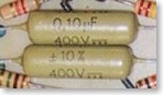
My favourites, and the most expensive, are the yellow
LCR metalised polypropylene axial (tubular) types. These are rated at 1000V
DC, and are suitable for connection directly across the mains (although
proper Class X suppressers should really be used). They are similar sizes
to the wax-coated paper types. They are available from CPC, RS and others.
Click the links for the CPC
order codes and
RS order codes. |
 |
RS Components also stock a range of yellow polyester
axial capacitors made by Vishay-Roderstein. These are available in 63V,
250V and 400V DC ranges, the 250V and 400V types being the most suitable
for our needs (250V is adequate in most positions and is smaller). They
are smaller than the LCR types, making them ideal for replacing the Hunts
Mouldseal capacitors. They are also cheaper, making them a good general-purpose
range, but they are NOT suitable for connecting across the mains. Click
the link for the RS
order codes. |
 |
The cheapest option is dipped polyester. RS and CPC stock
the BC Components (formerly Philips) 368 series dipped polyester. These
are orange epoxy dipped polyester components, with short leads intended
for PCB mounting. The 250V DC and 400V DC types are suitable for use in
valve equipment but the leads will often need to be extended. They are
cheap and work OK, but are fiddily to use and look untidy, so they are
not recommended. I use these if I am doing a repair for a paying customer
who wants the job done cheaply! They are NOT suitable for connection across
the mains. Click the links for the CPC
order codes and RS
order codes.
|
 |
CPC also stock a low cost range of dipped polyesters made by Samwha,
which is a bit cheaper than the BC Components variety. Being a redish-brown
colour they don't stand out quite as much as the orange BC Components
ones. Click the link for the CPC
order codes.
|
 |
CPC also stock Samwha dipped polypropylene 630V capacitors
in 0.022uF, 0.047uF and 0.1uF only. These are a bit easier to use than
the dipped polyester types above because the leads are longer. Unfortunately
0.01uF is not available in this range. As with the dipped polyesters,
I use these for "cheap" jobs, such as low cost sets with rough
cabinets that are never going to be brilliant but that I want to work.
Click the link for the CPC
order codes.
|
 |
For any position where a capacitor is connected across the
mains or is subjected to similar AC voltages, Class X2 suppresser capacitors
must be used. If the failure of the capacitor could put the user in danger
(such as a blocking capacitor in line with an aerial, earth or gram socket
on an AC/DC set) a Class Y suppresser must be used to comply with electrical
safety regulations. A number of manufacturers make similar products, the
order codes given here are just typical samples. Click the links for CPC
Class X2 order codes, CPC
Class Y order codes, RS
Class X2 order codes and RS
Class Y order codes.
|
 |
I have seen these blue LCR capacitors at swapmeets occasionally,
and been offered them by a dealer, but I cannot find them listed in any
of the current component suppliers catalogues, and there is nothing quite
like them on the LCR
website. They are somewhat scruffy looking components rated at either
1000V or 1250V. So far I have only seen them in 0.1uF and 0.22uF. They
are somewhat smaller than the yellow polypropylene types. The only problem
with them is that the leads (which are fairly thin) drop off if you don't
handle them with care.
|
The order codes and prices are taken from the
2002 CPC catalogue and the
RS September 2001 CD-ROM catalogue.
This information is included for reference only and is not intended as an endorsement
of these two companies above other suppliers. All prices exclude VAT and delivery.
Note that the RS order code and price is for one part, although many parts come
in packs of more than one (indicated by SSM - standard supply multiple - figure)
and you have to order in those multiples. CPC order codes are per pack of parts,
but the price is per part (you order the number of packs you want not the number
of parts).
The replacement capacitors may not be available
in exactly the same capacitance values as the original components. This is not
normally a problem, simply fit the closest available. For example, a new 0.047uF
component could be used to replace a faulty 0.04uF or 0.05uF capacitor.
The original capacitors (in particular wax-paper
types) may have a ring marked on one end. The ring normally indicates which
end the outermost layer of foil is connected to. This allows it to be mounted
the appropriate way round so that this outer layer acts as a screen, reducing
noise pickup etc. It would generally be connected to chassis or the lowest impedance
side of the circuit. New caps won't have this ring, so it doesn't matter which
way round they are fitted.
Most of the original capacitors had a tolerance
of +/-10%, and in many cases the values are not critical. When the capacitors
are used in tone control or tone correction circuits the value is more critical
and it is worth using replacements that are closer in value.
Some restorers like to fit the modern replacement
capacitor inside the case of the old one, which leaves the underside of the
chassis looking original. I have never attempted this because I feel it is really
not worth the effort.
Nigel Hughes made the following comments:
In some early radios, the troublesome capacitors
are contained in shiny card tubes sealed with pitch at each end. I have found
it possible to melt out the pitch with a soldering iron and pull the old guts
out of the tube with a pair of pliers. When melting out the pitch, let it
run out on to a sheet of metal. You will be able to remove the blobs quite
easily and use them again later. Modern replacements are much smaller than
the originals and can be put back inside the original tubes and the ends sealed
up with the pitch. This can leave the under-chassis appearance unaltered from
original.
Low Value Capacitors
I very rarely have to replace the low-value capacitors
(below about 0.01uF) because they tend to be reliable, and when I do replace
them it is generally with components from scrap sets.
However a recent visitor asked for suggestions
for new replacement components, so I loaded up the RS catalogue CD-ROM and had
a quick look for likely types:
 |
Resin Coated High Voltage Disc Ceramic - 118-713 etc.
Reasonable lead length, fairly small cases, 100pF to 4700pF available in
1kV and higher, prices 11p to 26p each, supplied in multiples of 10. Click
the links for CPC
order codes and RS
order codes. |
 |
Polystyrene - 113-207 etc. Cheap, values from 10pF to
10,000pF, but only rated at 160V. Should be fine in many positions, and
will probably fit in better than the disc ceramics above. The coloured end
indicates the outer foil layer. Although the capacitors are not polarised,
it makes sense to regard the coloured end as the negative terminal when
fitting. Click the links for CPC
order codes and RS
order codes. |
 |
Silver Mica - 495-593 etc. 2.2pF to 47,000pF, 500V rated,
high precision and stability, but expensive. Probably more suitable for
expensive SW communications sets etc., rather than a more normal broadcast
receiver. Click the link for RS
order codes. |
And that's about the lot! I reckon it's the Polystyrene
unless voltage is an issue. Does anyone have any other thoughts or comments
on this?
Electrolytic Capacitors
Electrolytics are also prone to failure, particularly
the large smoothing cans. The tests detailed previously should help to reform
some of these, but a few will need to be replaced. High voltage electrolytics
are expensive, but you will only need two or three in an average set. Again
if I am carrying out a repair for a paying customer, I am inclined to replace
all the electrolytics regardless, particularly if the set has not been used
for some time.
The cans are not available now. Until a couple
of years ago many of the major component suppliers offered a range of useful
values at competitive prices, but these have now been discontinued (apparently
LCR have stopped making electrolytics). Valve radio dealers sometimes stock
something suitable, generally NOS (new-old-stock), but supplies tend to come
and go so it may be worth buying a couple more than you need when they are available.
The usual approach if you cannot obtain a suitable
can is to fit replacement modern axial capacitors below the chassis and leave
the old can, disconnected, on the chassis so it looks correct. Some restorers
remove the innards from the original cans and fit the modern replacement capacitors
inside.
After reading this paragraph, Nigel Hughes made
the following comments:
With regard to electrolytics, the set I
restored recently had a wet type reservoir capacitor that had leaked at some
time, leaving a mushroom growth on the can seals. I thought it better not
to put modern electrolytics under the chassis leaving the leaky can in place,
so in this case I would always recommend gutting the can and inserting a modern
dry electrolytic inside. Modern types are generally much smaller than the
originals and there seems to be plenty of space.
The availability of suitable modern capacitors
can only get worse, because there seems to be a decreasing requirement for high
voltage electrolytics with a decent ripple current rating in modern electronics,
so the range of these capacitors produced continues to drop. Anyone who works
in electronics will know that the capacitor manufacturers seem to change their
ranges with infuriating regularity (in an continuous push to make them smaller
and able to operate at higher frequencies) so the types shown below should be
regarded as suggestions only, and the current suppliers catalogues or websites
consulted to find out what is currently available.
 |
RS Components and many other component suppliers stock
a range of 450V axial electrolytics in values from 1uF to 47uF which should
cover most eventualities. Axial (one lead from each end) are more suitable
for connecting underneath the chassis because they won't flap about as much
as radials (both leads from the same end). RS currently stock a couple of
different types, standard 85°C types and long-life 105°C versions.
The long-life ones are naturally a lot more expensive. Click the links for
RS 85°C order
codes, RS 105°C
order codes and CPC
85°C order codes. |
 |
Radial electrolytics are intended for PCB mounting. They
are more commonly available than axials, although as mentioned above the
range does seem to be reducing. They would be a good choice for fitting
inside the original can because all the leads are at the same end. As
with the axials, there are standard and long-life versions available.
Click the links for RS
85°C order codes and RS
105°C order codes.
|
An important consideration with replacement electrolytics
in smoothing applications is the "ripple current" rating. In normal
use as a smoothing capacitor it will be charged on the peaks of the input cycle
and discharging as it supplies the load for the rest of the cycle. Current will
therefore be flowing in and out of the capacitor all the time. This is the ripple
current. The discharge current will be the load current and will be relatively
constant, while the charge current which only occurs briefly will be fairly
high. The best we can do is assume the average ripple current is a little higher
than the total HT current drawn by the set, and make sure the capacitor - in
particular the main smoothing capacitor on the rectifier output - has a ripple
current rating greater than that.
Looking at the ripple current rating of the 22uF
450V devices in the samples given above (a suitable replacement value for a
typical 16uF 375V smoothing cap), most are around 180mA - 210mA which should
be fine for a typical set consuming about 60mA HT.
However one of the devices (the 105°C radial)
has a ripple current of only 115mA, which illustrates the point I was making
above about difficulties in finding suitable modern components for our needs.
In this series the 10uF 450V has a 75mA ripple current rating, so you would
get a better rating by using two of these in parallel (150mA). For the later
decoupling stages the ripple current is much lower, so there shouldn't be any
problems.
Home
This website, including all text
and images not otherwise credited, is copyright © 1997 - 2006 Paul Stenning.
No part of this website may be reproduced in any form without prior written
permission from Paul Stenning.
All details are believed to be accurate, but no liability can be accepted for
any errors.
The types of equipment discussed on this
website may contain high voltages and/or operate at high temperatures.
Appropriate precautions must always be taken to minimise the risk of accidents.
Last updated 14th April 2006.